Building Your First Circuit
Understanding schematics
We must understand that there are two distinct representations of a circuit:
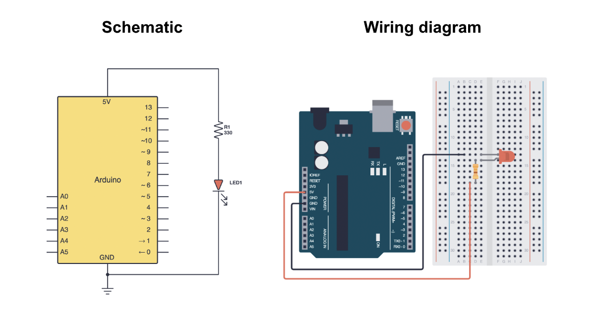
- Schematic - a blueprint of your circuit which uses symbols to represent components.
- Wiring diagram - a wiring or breadboard diagram shows how to connect parts on a physical breadboard.
Engineers communicate using schematics, not wiring diagrams.
Often, in tutorials, wiring diagrams are provided to help beginners easily construct circuits. However, following a wiring diagram is like following a LEGO kit. It gets the job done, but it doesn't teach you how the circuit works.
Since we will be using schematics frequently, it's essential that we understand how to work with them.
Symbols
Read this article by SparkFun Electronics to familiarise yourself with the various schematic symbols. Don't worry about memorising all of them for now; you will slowly get used to them as you encounter more circuits.
Translating a schematic to the breadboard
The next step is to go from a schematic to an actual circuit on your breadboard. Remember to follow these steps when translating a schematic to a circuit:
- Identify the components in your schematic and gather them. If you're struggling to remember what component a symbol represents, you can refer back to this helpful guide.
- Arrange the components on the breadboard neatly, making sure any polarized components are connected in the direction of current flow.
- Wire the connections using jumper wires. You can use the breadboard's side rails to connect to 5V and GND if you're powering many components.
- Carefully double check your connections. Ensure components are not in the same row as this could result in a short circuit!
- Begin programming!
This might seem complicated now, but it will make a lot more sense once we take a look at connecting the LED.
The LED
A light emitting diode (LED) is a component that emits light when current passes through it. As the name implies, an LED is a diode, which means it only allows current to flow through it in one direction. Watch this video if you want to understand how LEDs work.
LEDs can burn out if too much current passes through them. To prevent this from happening, we generally connect a current-limiting resistor in series with our LED to limit the amount of current flowing through it.
LED polarity
LEDs are polarized components, which means they have designated positive and negative terminals. Polarized components must be connected in a specific direction to function correctly. If we do not connect a polarized component correctly, we risk causing damage to it.
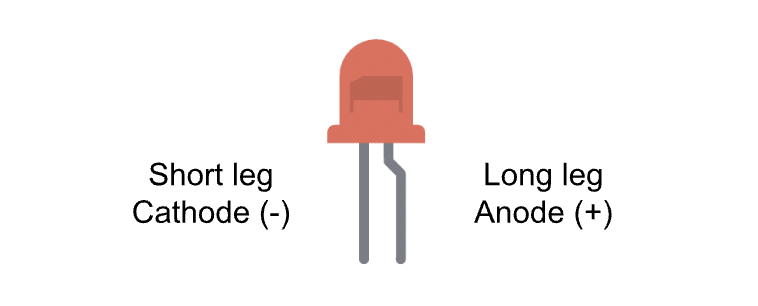
- The long leg, known as the anode, is the positive side of the LED. We usually connect this long leg to an Arduino digital pin or 5V.
- The short leg, known as the cathode, is the negative side of the LED. We usually connect this short leg to
GND.
Current always flows from the anode to the cathode, and never the opposite direction.
Constructing a simple LED circuit
Components required:
- 1x LED (any color of your choice)
- 1x 220Ω resistor
- Breadboard
- A handful of jumper wires
- Your Arduino Uno
- Problem
- Solution
This is the first of many Try It Yourself sections you will encounter throughout this course. These are mini-assignments for you to test the knowledge you have gathered previously. Ensure you only click on the Solution once you've tried to solve the Problem yourself.
For this problem, try to construct a simple LED circuit on your breadboard using the schematic below. Make sure that the longer leg of your LED (anode) connects to digital pin 2. We will use this pin as an output when programming. Refer to the this guide if you're struggling to remember what a circuit symbol represents.
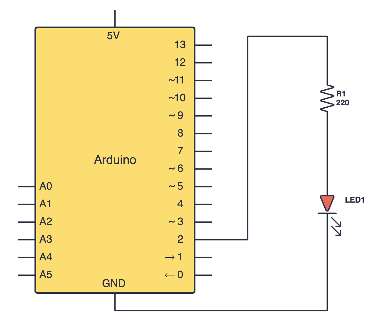
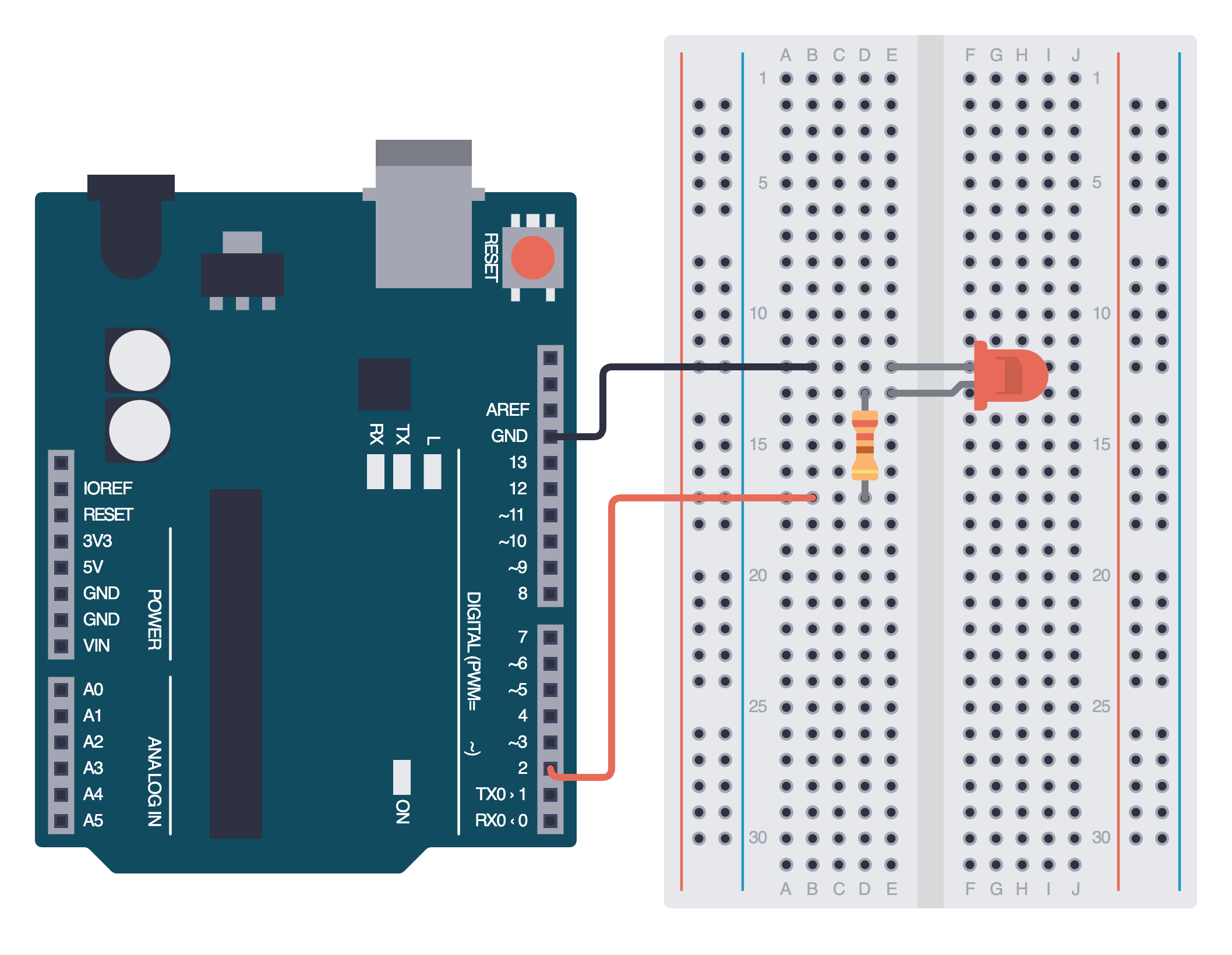
If your physical circuit doesn't exactly match the wiring diagram below, don't worry; there are many possible representations of a schematic on a breadboard. Just ensure that the shorter leg (cathode) of your LED connects to GND, and the longer leg (anode) connects to digital pin 2.
Controlling the LED using code
To turn an LED on or off, we need to send a HIGH or LOW signal to our LED. We can create a simple sketch to blink our LED by sending these signals.
int LEDPin = 2; // Using a variable to store our digital pin
int delayTime = 1000; // Using a variable to store our delay time

void setup() {
  pinMode(LEDPin, OUTPUT); // Set pin 2 as output
}

void loop() {
  digitalWrite(LEDPin, HIGH);  // Turn LED on
  delay(delayTime); // Wait 1 second
  digitalWrite(LEDPin, LOW);   // Turn LED off
  delay(delayTime); // Wait 1 second
}
There are a few main functions in the sketch above we must understand:
pinMode()- used to configure a pin as an INPUT or an OUTPUT. For example,pinMode(5, INPUT);would configure digital pin 5 as input.digitalWrite()- used to send a HIGH or LOW signal to a digital pin. For example,digitalWrite(4, LOW);turns digital pin 4 off.delay()- used to pause the program for a given amount of time in milliseconds. We encountered this function earlier.
If you can't remember how a function works, refer to the Arduino docs. Every new function we come across will be linked with the respective documentation.
Write out this code for yourself, and make sure you understand how each line works. Then, upload your sketch to your Arduino board. Congratulations, you have controlled your first LED!
Assignment
- Going forward, we will wire components without a wiring diagram. Get familiar with reading schematics and translating them into wiring diagrams through this video.
- Remove all of your connections from the breadboard. Rebuild the same circuit, but use another digital pin this time. Also, try decreasing the delay time. What do you notice?
Next Steps
This section includes links to help you dive deeper into the topics from this lesson. It's optional, so don't worry if you choose to skip it.