The RGB LED
An RGB (Red-Green-Blue) LED is is like 3 LEDs in one. We can use an RGB LED to produce a variety of colors by mixing different intensities of red, green and blue light. Search up RGB LED online to understand what one looks like.
How it works
An RGB LED has 4 pins - one for each color (R, G, B) and a common pin. The common pin is the longest pin on your RGB LED and goes to GND or 5V depending on whether you have a common cathode or common anode RGB LED.
We'll assume you're using a common cathode RGB LED for this lesson, and we'll connect the common pin to GND. If you have a common anode RGB LED, just connect the common pin to 5V instead.
Constructing your circuit
Components required:
- 1x RGB LED
- 3x 220Ω resistor
- Breadboard
- Jumper wires
- Your Arduino Uno
- Problem
- Solution
Search up your RGB LED's datasheet online. Datasheets will be your friend when learning about new components since they provide all the necessary information you will need to construct your circuit.
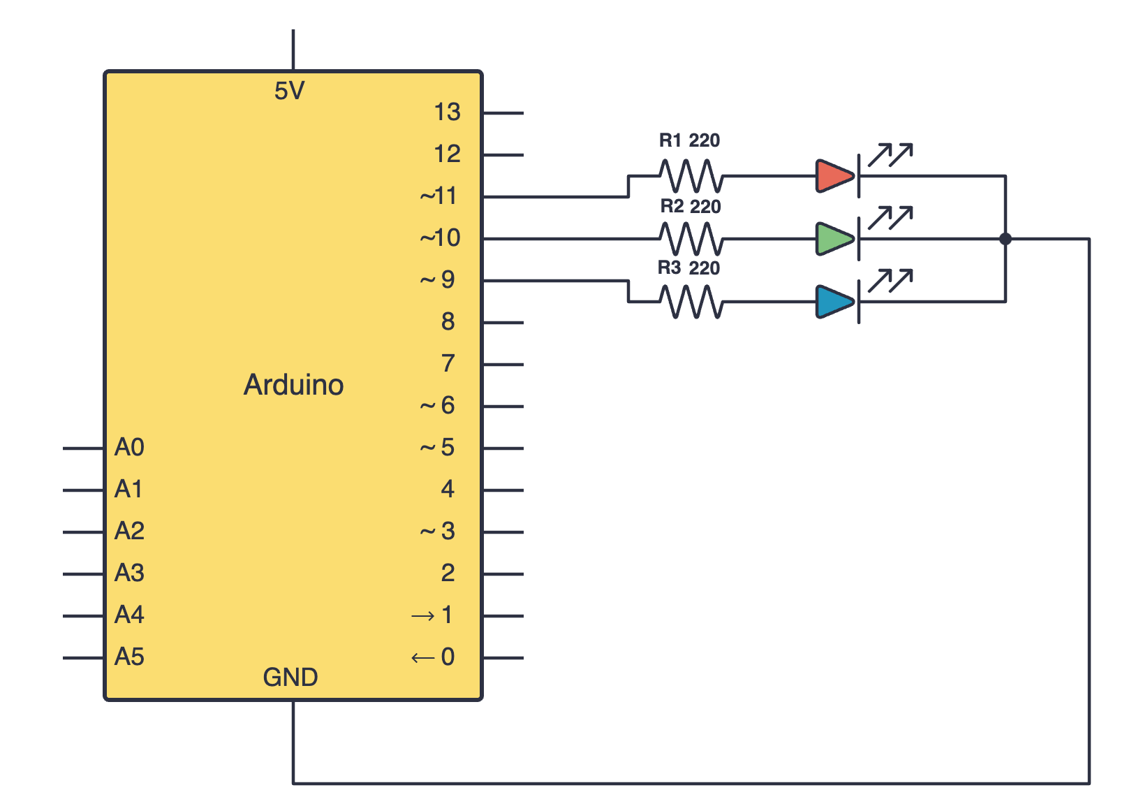
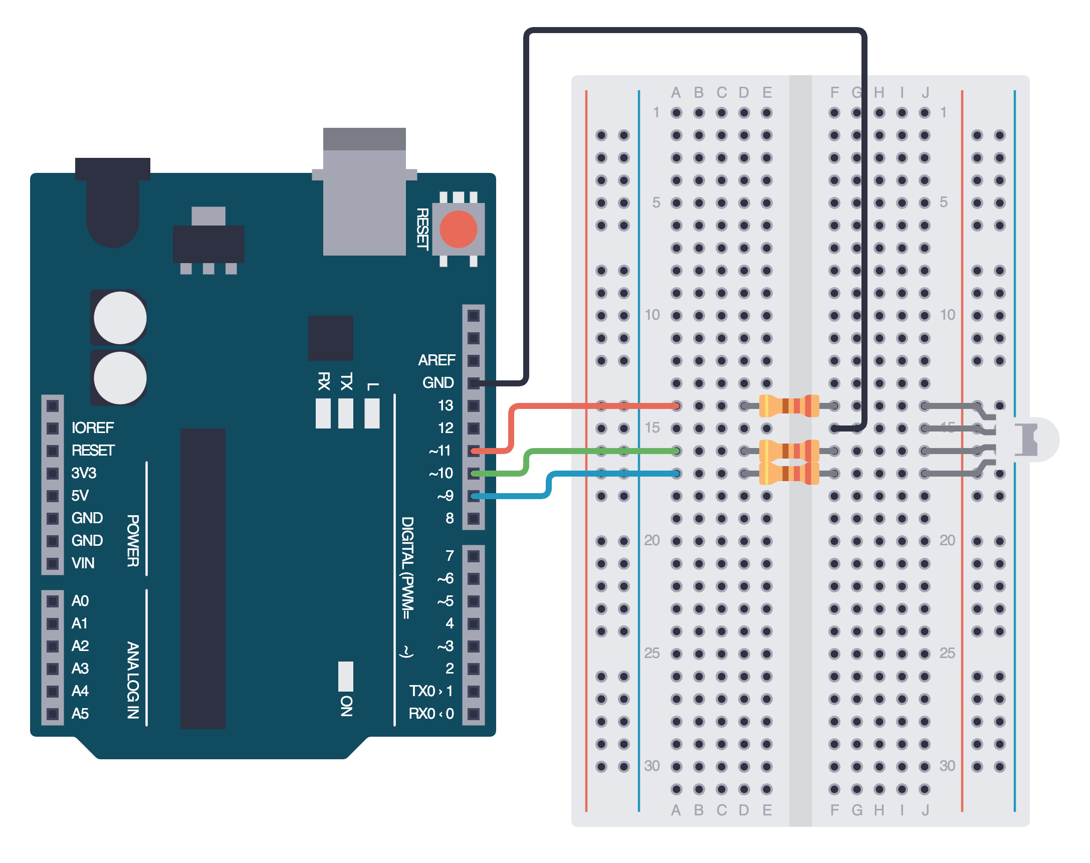
Try building your circuit using the schematic above. Notice we have connected the red, green and blue legs of the LED to pins marked with a ~ on an Arduino. Do you remember why we use these pins?
Below is the equivalent circuit diagram for this schematic. Did you hook up your components correctly?
Programming your RGB LED
Now that you've wired up your RGB LED, it's time to program it to blink. Each color pin (R, G, B) behaves just like a regular LED, and you can turn it on and off by sending a HIGH or LOW signal. For example, the sketch below can be used to cycle through red, green and blue every second.
int redPin = 9;
int greenPin = 10;
int bluePin = 11;

void setup() {
  pinMode(redPin, OUTPUT);
  pinMode(greenPin, OUTPUT);
  pinMode(bluePin, OUTPUT);
}

void loop() {
  digitalWrite(redPin, HIGH);   // Red on
  digitalWrite(greenPin, LOW);
  digitalWrite(bluePin, LOW);
  delay(1000);

  digitalWrite(redPin, LOW);
  digitalWrite(greenPin, HIGH); // Green on
  digitalWrite(bluePin, LOW);
  delay(1000);

  digitalWrite(redPin, LOW);
  digitalWrite(greenPin, LOW);
  digitalWrite(bluePin, HIGH);  // Blue on
  delay(1000);
}
Mixing colors
Alternatively, since we've connected our color pins to pins that support PWM, we can use these to send a PWM signal and vary the brightness of each color. This can then be used to mix colors.
- Problem
- Solution
Pick your favorite color using this RGB color picker. Note down the R, G, B values and use the analogWrite() function to mix colors to obtain your favorite!
This is an example sketch to display the color Turquoise.
int redPin = 9;
int greenPin = 10;
int bluePin = 11;

void setup() {
    pinMode(redPin, OUTPUT);
    pinMode(greenPin, OUTPUT);
    pinMode(bluePin, OUTPUT);
}

void loop() {
    analogWrite(redPin, 64);
    analogWrite(greenPin, 224);
    analogWrite(bluePin, 208);
}
Assignment
- Write a program to make your RGB LED cycle through different colors. Choose three colors of your choice and make each of them fade in and out slowly, one after the other. Remember to use the
delay()function.
Next Steps
This section includes links to help you dive deeper into the topics from this lesson. It's optional, so don't worry if you choose to skip it.
- Here is a tutorial video on RGB LEDs you can watch.