Understanding PWM
Until now, we have learnt how to turn an LED either fully on (by supplying 5V), or off (by supplying 0V). Pulse Width Modulation (PWM) is useful in many different applications, but for now, just remember it can be used to vary the brightness of an LED.
What is PWM?
Pulse Width Modulation (PWM) is a technique which generates a continous HIGH and LOW alternating signal by turning a pin on and off extremely fast.
PWM works by sending a PWM signal, which is essentially a square wave. This is what a PWM signal looks like:
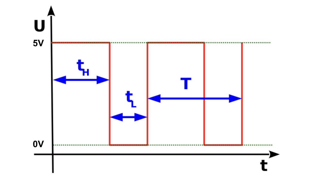
As you can see, the wave spends a varying amount of time in 5V and 0V which represent the HIGH and LOW states respectively. There are a few terms in the diagram above that you should understand:
- tH - time for which the signal is
HIGH - tL - time for which the signal is
LOW - T (Period) - total time for which the signal is
HIGHandLOW. Therefore, it is tH + tL.
Duty cycle
A duty cycle is the fraction of time for which a signal stays HIGH (tH) during one complete period (T). Essentially, it tells us how long the pin stays on compared to how long it stays off. Therefore,
- A 100% duty cycle would mean that an LED is fully on.
- A 50% duty cycle would mean that an LED is dim.
- A 0% duty cycle would mean that an LED is always off.
Using PWM with an LED
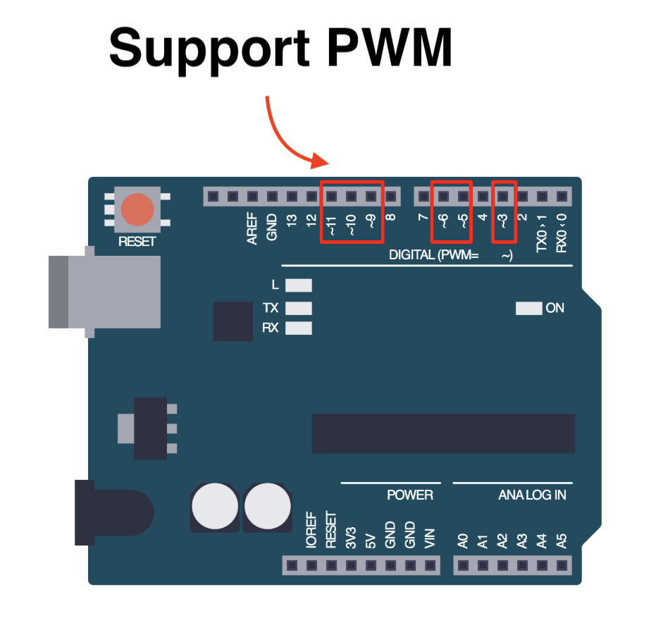
We can use PWM to vary the brightness of an LED by writing an analog value (PWM signal) to a pin. Note that not all pins are capable of supporting PWM. We have to use pins that are marked with a ~.
analogWrite()
To write a PWM signal to a pin, we use the analogWrite() function.
analogWrite(pin, value);
- The
valuerepresents the duty cycle - between 0 (always off) and 255 (always on). This is because Arduino uses an 8-bit resolution for theanalogWrite()function. This means that:analogWrite(pin, 0)results in a 0% duty cycle.analogWrite(pin, 255)results in a 100% duty cycle.
Let's try to create an example program where we dim an LED and then increase the brightness. The following example has the LED connected to pin ~9 since it supports PWM.
void setup() {
  pinMode(9, OUTPUT);
}

void loop() {
  analogWrite(9, 50);   // Dim light
  delay(1000);
  analogWrite(9, 200);  // Increase brightness
  delay(1000);
}
Assignment
- Connect an LED to a pin on your Arduino board that supports PWM. Ensure you hook up your circuit correctly.
- Write a program to fade the LED on and off using the
analogWrite()function you have learnt. Hint: you will have to use aforloop.
Next Steps
This section includes links to help you dive deeper into the topics from this lesson. It's optional, so don't worry if you choose to skip it.
- This video explains PWM well. Check it out.