Push Buttons
A push button is a simple and handy component we can use to take user input into our projects. They work by completing a circuit when pressed, and opening (breaking) it when the button is released. They don’t have polarity, so they can be connected in either orientation.
How it works
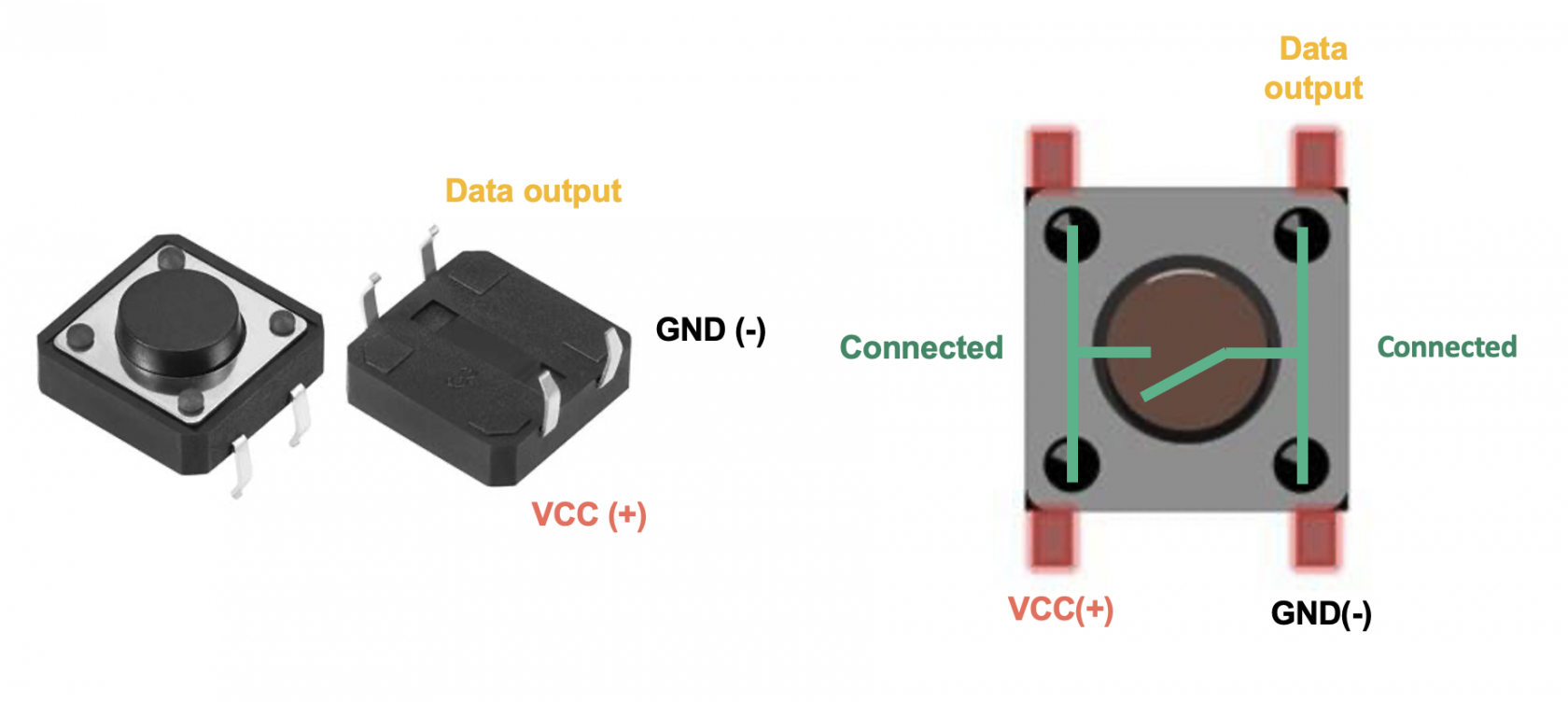
A push button consists of 4 pins - with 2 on either side being internally connected. When the button is pushed, the two sides are connected, allowing current to flow and complete the circuit. When the button is not pressed, these pairs of pins are not connected.
Pull-up and pull-down resistors
When we connect a push button to our Arduino board input pin, the input can be floating. This means that the microcontroller reads unpredictable values since it cannot decide firmly between HIGH and LOW.
To go around this problem, we must use a pull-down or pull-up resistor:
- Pull-down resistors connect between the input pin and GND.
- When the button isn't pressed, the input reads
LOW(0V), and when the button is pressed, the input readsHIGH(5V).
- When the button isn't pressed, the input reads
- Pull-up resistors connect between the input pin and 5V.
- When the button isn't pressed, the input reads
HIGH(0V), and when the button is pressed, the input readsLOW(5V).
- When the button isn't pressed, the input reads
Luckily, Arduino's digital pins have in-built pull-up resistors which we can use without having to connect external resistors. To do this, we must set the pinMode() to INPUT_PULLUP.
pinMode(buttonPin, INPUT_PULLUP);
Constructing your circuit
Components required:
- 1x Push button
- Your Arduino board
- Breadboard
- Jumper wires
- Problem
- Solution
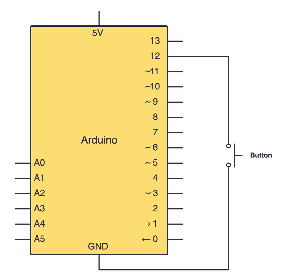
Search up your push button's datasheet online. Datasheets will be your friend when learning about new components since they provide all the necessary information you will need to construct your circuit. Try building your circuit using this schematic:
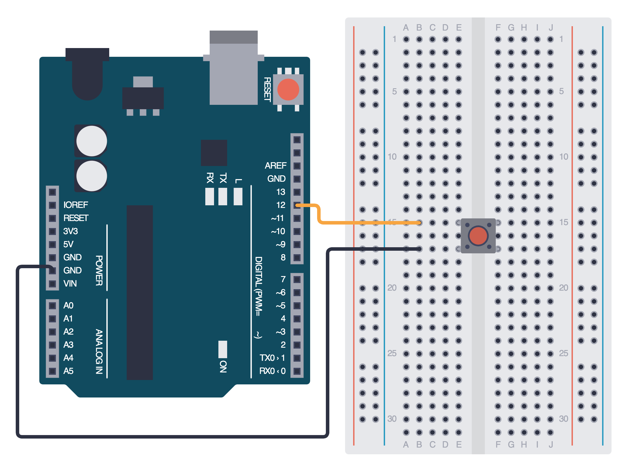
Below is the equivalent circuit diagram for this schematic. Did you hook up your components correctly?
Programming your push button
Once you've connected your push button using the schematic above, we will program it. To do this, we will use the digitalRead() function and print a message to the serial monitor:
int buttonPin = 12;  // Push button connected to pin 12
int buttonState;

void setup() {
  pinMode(buttonPin, INPUT_PULLUP);  // Enable internal pull-up resistor
  Serial.begin(9600);
}

void loop() {
  buttonState = digitalRead(buttonPin);
  if (buttonState == LOW) {
    Serial.println("Button Pressed");
  } else {
    Serial.println("Button Released");
  }
  delay(200);
}
Assignment
- Build a simple push button circuit in which an LED is on when the button is pressed, and off when the button is not pressed.
Try to create a toggle switch for turning this LED on and off. You can look for help online if stuck.
Next Steps
This section includes links to help you dive deeper into the topics from this lesson. It's optional, so don't worry if you choose to skip it.
- Read this to learn more about pull up and pull down resistors.