DC Motors
The third type of motor we will learn about is the DC motor (direct current) motor. Unlike stepper motors, which move in precise steps, or servo motors, which move to specific angles, a DC motor can spin continously when powered.
How it works
A DC motor uses the motor effect from electromagnetism to convert electricity into mechanical energy (movement). It consists of two terminals; when current flows in one direction, the motor spins forwards, but when the current is reversed, the motor spins backwards. The speed of a DC motor depends on how much voltage is applied.
Just like stepper motors, we cannot connect a DC motor directly to our Arduino board. Instead, we have to use a motor driver such as the L298N or L293D module and a power supply module.
Constructing your circuit
Components required:
- 1x DC Motor
- 1x External power supply - we will be working with a power supply module
- 1x L293D module (motor driver)
- Jumper wires
- Arduino board
- Breadboard
- Problem
- Solution
Search up your DC motor, motor driver and power supply module's datasheet and pinout online. Try building your circuit using this pin layout:
- DC motor connections to L293D
- Motor terminal 1 → OUT1 (L293D pin 3)
- Motor terminal 2 → OUT2 (L293D pin 6)
- L293D connections to Arduino
- IN1 (pin 2) → Arduino D4
- IN2 (pin 7) → Arduino D3
- EN1 (pin 1) → Arduino D5 (PWM pin for speed)
- GND (pins 4, 5) → Arduino GND
- Vs (pin 8) → + from Power Module (9V–12V)
Below is the equivalent circuit diagram for this schematic. Did you hook up your components correctly?
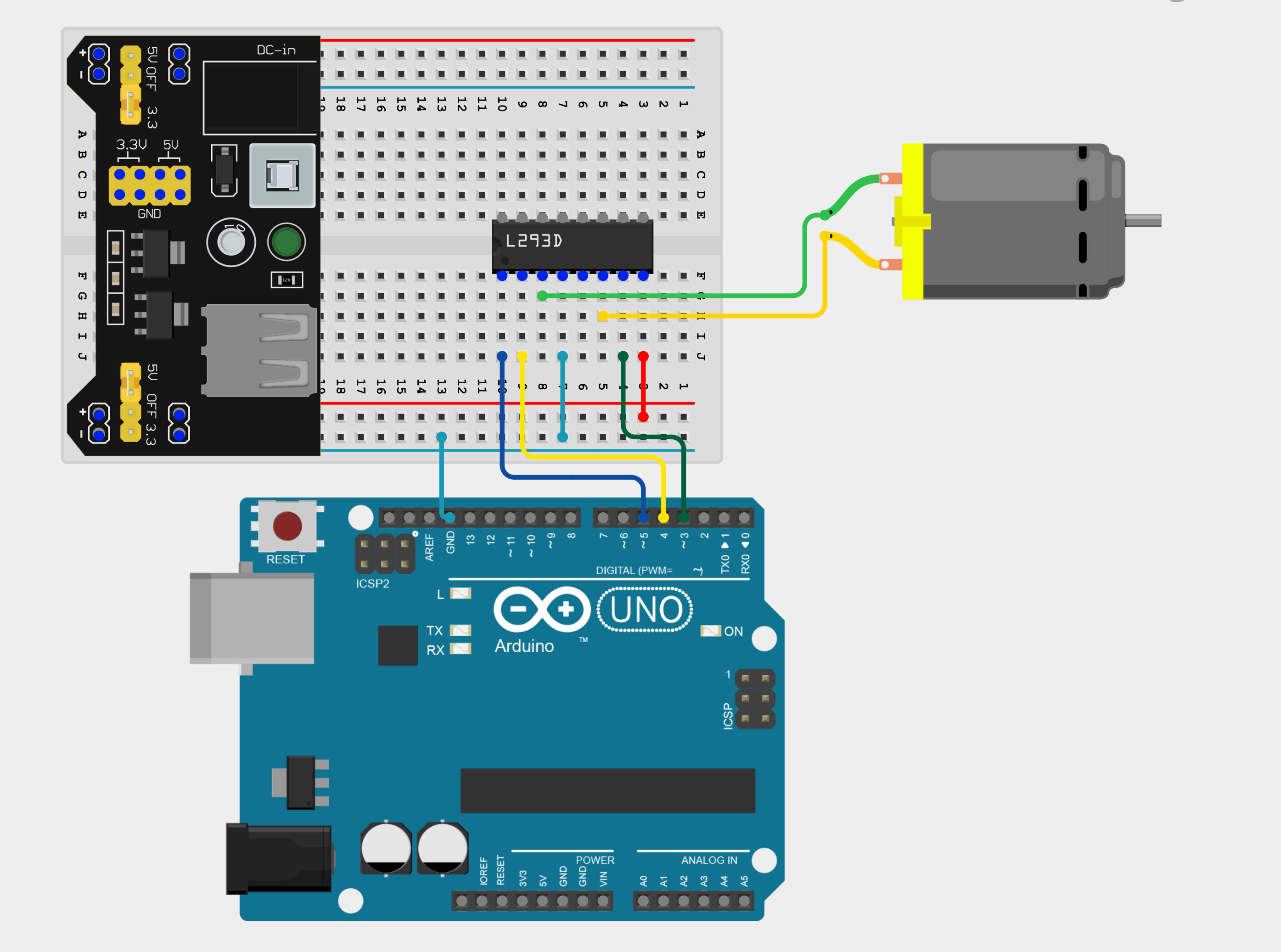
Notice we have only used one side of the L293D motor driver chip. This is because the chip can control two DC motors at the same time, but we are only controlling one motoro for now.
Programming your DC motor
Now that we've wired the DC motor with the motor driver, let's write code to control it's direction and speed.
Making our motor spin
To make our DC motor spin, we have to first define some constants:
#define ENABLE 5 // Pin 5 is connected to the L293D's EN1
#define DIRA 3 // Controls the forward direction
#define DIRB 4 // Controls the reverse direction
In our setup(), we then set all pins as outputs and in our loop() we use digitalWrite() to turn on our motor. The entire sketch, therefore, is as follows:
#define ENABLE 5
#define DIRA 3
#define DIRB 4

void setup() {
  pinMode(ENABLE, OUTPUT);
  pinMode(DIRA, OUTPUT);
  pinMode(DIRB, OUTPUT);
}

void loop() {
  // Spin forward
  digitalWrite(ENABLE, HIGH);
  digitalWrite(DIRA, HIGH);
  digitalWrite(DIRB, LOW);
  delay(2000);

  // Spin backward
  digitalWrite(DIRA, LOW);
  digitalWrite(DIRB, HIGH);
  delay(2000);

  // Stop motor
  digitalWrite(ENABLE, LOW);
  delay(2000);
}
Controlling the motor's speed
Instead of just turning the motor ON/OFF, we can also use PWM using analogWrite() instead of digitalWrite() with a range of 0 to 255 to control the speed of the motor.
#define ENABLE 5
#define DIRA 3
#define DIRB 4

void setup() {
  pinMode(ENABLE, OUTPUT);
  pinMode(DIRA, OUTPUT);
  pinMode(DIRB, OUTPUT);
}

void loop() {
  // Set motor direction (forward)
  digitalWrite(DIRA, HIGH);
  digitalWrite(DIRB, LOW);

  // Ramp up speed
  for (int speed = 0; speed <= 255; speed += 50) {
    analogWrite(ENABLE, speed);
    delay(1000);
  }

  // Ramp down speed
  for (int speed = 255; speed >= 0; speed -= 50) {
    analogWrite(ENABLE, speed);
    delay(1000);
  }

  delay(2000);
}
Assignment
- Connect a push button and a potentiometer to your Arduino board. Then, create a sketch which makes your motor spin forward when the button is pressed, and backward when the button is released. Use your potentiometer to vary the speed of your DC motor. Remember to use
map()!
Next Steps
This section includes links to help you dive deeper into the topics from this lesson. It's optional, so don't worry if you choose to skip it.
- This page explains what H-bridges are.